_____________________________________________________
DISCLAIMER: I am not claiming that the information is this article is error free, so use it at your own risk. This article represents my understanding of the original paper by Sheik-Bahae, et. al., at the time of the article's writing. I have found flaws in the way I had understood the paper, since. My main motive for writing the paper was to let out my frustrations at my experiments, and this was the closest I had to having a person to talk to, for me to vent. Perhaps acting on misunderstood instructions exacerbated the situation, at the time, but this article, essentially, one frustrated graduate student's extra long rant.
_____________________________________________________
Here are my instructions (my tutorial) for doing a z-scan.
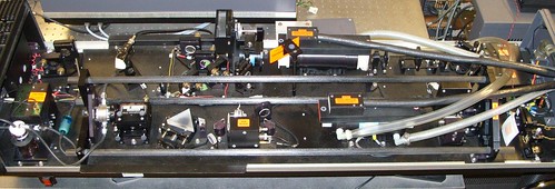
Okay, so I (we) finally got the laser (Continuum PY61C Nd:YAG picosecond pulse laser) working properly, and got our closed aperture z-scans!
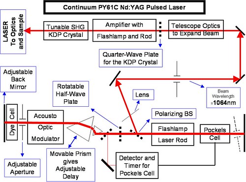
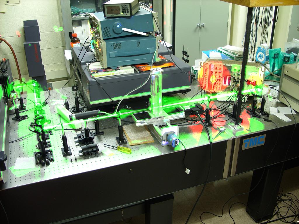
Here are the steps for setting up the laser, roughly (click on any image, to enlarge):
- Clean the dye system's internals, a few times, using fresh dichloroethane (laser grade).
- Put the laser in free run.
- Find the lasing threshold.
- Optimize the laser's back mirror (the mirror to the left) for laser intensity, or, rather, photon count inside the cavity), and also stability -- observe on a slow oscilloscope.
- Optimize the prism position, for stability
- Repeat steps 4 and 5 iteratively.
- If necessary, optimize the aperture position, though you should not need to do that every time you set up the laser.
- Choose an oscillator flash lamp voltage: if your oscilloscope's electronics are sensitive enough, then just go two notches above the threshold; if not, then choose a voltage so that when you start q-switching the laser pulse train shows up on your fast oscilloscope -- you have to have prior knowledge, from bitter experience, for this, or you can find this out the hard way, as you go along.
- You will probably see longitudinal modes on your slow oscilloscope. Kill them by adding fresh solution of Q-Switch 1 laser dye to the dichloroethane reservoir. If there are none of these modes, then go to step 10.
- Now, inspect the laser in the fast oscilloscope. You should see a pulse train with a Gaussian envelope function. If the envelope function is not Gaussian, then re-optimize the laser optics (back mirror and prism). If you do not see a pulse train, at all (but you can confirm, on the slow scope, that the system is lasing), then you did not choose a high enough voltage to pump the flash lamp with (you goofed up on step 8), so you increase the voltage supplied to the oscillator flash lamp, by a notch, or two, and go back to step 9.
- Add more laser dye (Q-Switch 1) until you have only 8-9 pulses left in the Gaussian pulse train.
- Play with the rotation of the half-wave plate, the thickness of the obstruction to the photodetector that activates the Pockels Cell, and the timing of the gate of the Pockels Cell, to get a stable output beam (I won't go into the physics of this, as that is beyond the scope of this article). Your beam (check it with an IR card, once the beam exits the laser housing) should have a single lobe. More than one lobe, and your beam is unacceptable -- in that case, you will need to go back to playing with the back mirror and the delay prism.
- Now, you should have a beam that you can do a z-scan with -- it's fluctuations should be within plus/minus 10%.
Now, here's where my problem was, and the whole point of writing this article:
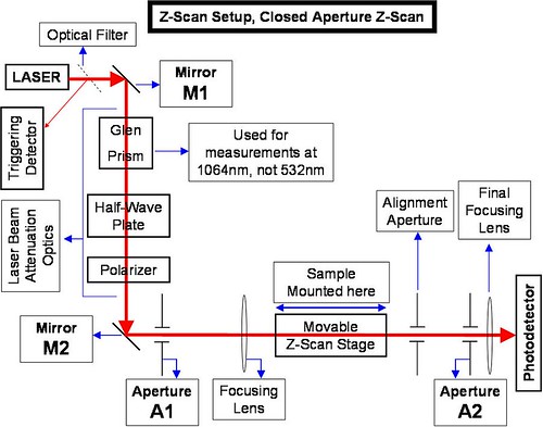
- When you get the beam past the polarizer, make sure that the beam characteristics do not change: make sure that you do not have more than one lobe in the beam that gets into the polarizer (if you do have more than one lobe, then go back to Step 12 of setting up the laser), and make sure the beam looks no different when it exits the polarizer (except in intensity) from when it enters the polarizer. If the beam looks different when it exits, then make sure the beam is not clipping off inside the polarizer housing, and if you see two lobes in the beam exiting the polarizer (remember, a beam with only one lobe went in) then you probably do not have the Glen Prism set correctly, as your beam is clearly not polarized in one direction, only -- i.e., your beam is probably circularly polarized, from when it went through the quarter wave plate that sits before the amplifier (this quarter wave plate is there because the KDP crystal that converts 1064nm to 532nm requires a circularly polarized beam, though the KDP crystal's output is a vertically polarized beam -- so, you will not need the Glen Prism if you are using 532nm).
- Have two apertures, for alignment purposes: one before the lens that focuses the collimated laser beam onto the sample, and one that sits as the final aperture, serving as the aperture during closed aperture z-scans.
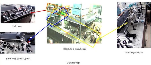
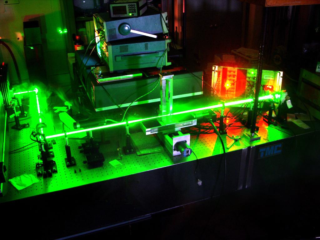
Personally, I have three apertures: one before the focusing lens (seen between the second mirror, and the focusing lens in the following picture -- o, and remember that the Glen Prism should not have been there, for the 532nm wavelength beam; and also note that while this article talks about doing a z-scan with a 1064nm beam, I chose to use a 532 nm wavelength beam for the pictures),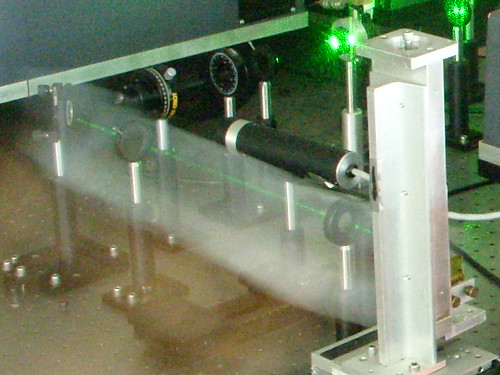
one after the sample (which I use for alignment purposes), and the final aperture, which I use during closed aperture z-scans. I do not touch the final aperture, during alignment, just so I have the personal satisfaction that the final aperture had the same diameter throughout the day, eventhough I may have had to realign the beam during the course of the day, to account for the beam's movement, as the ambient and equipment temperatures shift during the course of a day's operations. For the purpose of this article, though, I will only talk about two apertures: one for carving the beam (the one before the lens) and one for the closed aperture z-scan (the so-called final aperture). - Ensure that both the apertures are EXACTLY the SAME HEIGHT, and that they are bolted down in the exact same fashion/manner along the same line of screw holes on the optical table. That way, you can be sure the the apertures are aligned, and the any beam that goes through the centers of BOTH the apertures will be: (1) parallel to the surface of the table [and, thus, maintain its height], and (2) aligned along the screw holes. This second clause is important because the z-scan stage is mounted on the optical table, such that it's movements are aligned with the screw holes on the optical breadboard (optical table)
- Align the laser beam to go through the center of BOTH the apertures. Here is my painful way of doing it:
(1) Play with the first mirror (call it mirror M1, the one right after the laser housing, past the colored optical filter in the setup's picture) until the beam is as close as possible to the center of the first aperture (call it aperture A1, the one before the focusing lens).
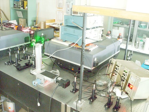
(2) Play with the second mirror (call it mirror M2, the one in the picture above, immediately past which I was able to 'illuminate' the path of the laser beam) to very finely position the beam at the center of A1. Ensure that the beam that gets through A1 is VERY CIRCULAR, by closing and opening the aperture, the check that the beam really does close in, on itself, as the aperture is closed. If the beam is not circular, to start with, then CARVE out a circular beam with this aperture A1, by closing the aperture just enough, but making sure that the beam which makes it past aperture A1
(a) is indeed very circular, and
(b) closes in onto its center, as the aperture is closed further.
VERY IMPORTANT NOTE: When doing step (2), of this section, it is NOT absolutely necessary that the point of highest intensity of the beam be at the center of the aperture. Your beam may even dim drastically, as you go across the diameter of the beam, from one point on its circumference to another; but that's okay! Pretty much anything goes, as long as
(i) your beam, past aperture A1, is circular, and
(ii) its intensity profile has only ONE GLOBAL MAXIMUM.
I know that my tone, in this paragraph, sounds rather prudish, but not being aware of this was what kept me from making progress for a very long time.
If you are doing a closed aperture z-scan, then, personally, I would try to make sure that the diameter that I settle on, for aperture A1, is at least twice the diameter that I will use for the final aperture; but that is just my personal bias.
(3) Repeat steps 1 & 2 of this section ITERATIVELY until you are very satisfied that the beam hits aperture A1 DEAD ON/PERPENDICULARLY.
(4) Follow the beam, and see if it hits the final aperture (call it aperture A2, the one past the sample).
(5) REPEAT steps 1, 2 & 3, centering the beam on aperture A2.
Note that the beam that hits aperture A2 will probably have a larger diameter than the beam that went through aperture A1 (it does, in our setup), because the beam hits the focusing lens, after going through aperture A1, and past its focus, it diverges. You might notice the 532 nm wavelength beam converging (towards the extreme right of the picture) here: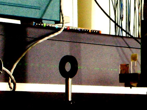
You should now have a very well aligned laser beam, at the scanning platform. - Now, you should be able to put a 1mm path length (or longer) quartz cuvette into the beam path (mounted on the z-scan stage) filled with carbon disulphide (we'll call it CS2, henceforth) and take a z-scan of it, to calibrate your setup. Make sure you have a way to repeatably start and stop your z-scans at the EXACT same points (right down to the stepper count of the stepper motor that you use to drive the z-scan stage), and take multiple calibration curves, just to be sure. Your CS2 curve should look like this:
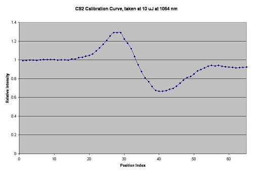
The symmetricity of the peak and dip (one should look like a reflection of the other, in the x-axis/abscissa, if the start and end points of the scan were placed at zero, on the ordinate) indicate good laser alignment and the smoothness of the curve confirms a stable beam. Once this curve has been obtained, it is confirmed that the z-scan setup is configured properly and hence, all z-scan work can proceed. - Take all your z-scan data, for all your samples, as well as at different points on each sample, just to be sure.
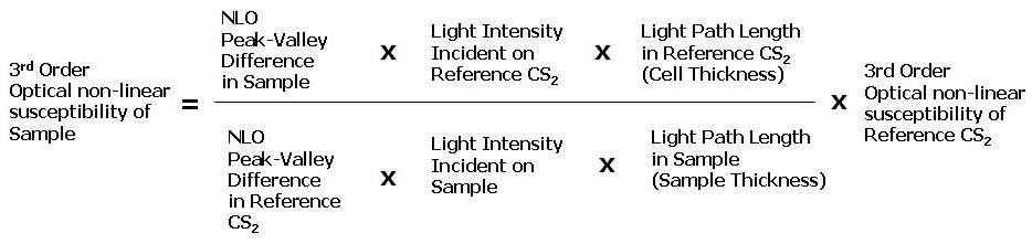
Here is the formula you can use to calculate the Chi3 (aka, 3rd order optical non-linearity susceptibility) of your samples, from your z-scan data:
There is a paper with some more nifty little formulae, including a data sheet of CS2 properties, here:
Third-order nonlinearities in GeSe2–In2Se3–CsI glasses for telecommunications applications
Optical Materials, Volume 31, Issue 1, September 2008, Pages 75-78
Another paper with other useful relationships is here:
Ultra fast third-order non-linear response of amino-triazole donor–acceptor derivatives by optical Kerr effect
Optics Communications, Volume 281, Issue 20, 15 October 2008, Pages 5239-5243
In the event that your samples have a high two photon absorption (TPA), take your readings at the intensity that you would expect to take your data, and then for every one of these readings increase the power (to increase TPA) and then repeat the same measurement. So, you should have two sets of readings for every position, for any given sample (one at a lower power, and one at a higher power). Last time, for example, we took one reading at 10 uJ of energy, and another at 20 uJ of energy for every point on the samples that we were testing. You can then use the following formula to subtract the TPA from the NLO (self lensing/intensity dependent refractive index change) curves:
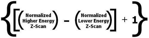
Once you get the curves from this formula you can use the above formula, for Chi3 (aka, 3rd order optical non-linearity susceptibility), plugging in the higher of the two beam energies used, for the "Light Intensity Incident on Sample" value, into it to get the Chi3 of your samples. I am not sure why the higher of the two energies is plugged in, but that was the number that gave me answers closer to the Chi3 value that I had calculated (for the same samples) in a previous experiment.
If all has gone well, then you should now be able to publish! Check with your professor, to find out.
No comments:
Post a Comment